Wer OSD (On Screen Display) für FPV mit Walkera iLook verwenden möchte, muss das Video der iLook Kamera herausschleusen, über das OSD Modul (z.B. MinimOSD) führen und dann wieder in die Kamera bringen, damit das Video von dem integrierten 5,8 GHz Sender übertragen werden kann.
Wir müssen also das AV-out der Kamera rausführen und vom OSD-Modul zum internen Sender führen. Es müssen somit 2 x 2 Litzen aus dem Gehäuse geführt werden. Ein 3mm-Loch, das in die Kamera gebohrt werden muss, reicht dafür.
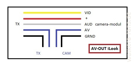
Wir brauchen für das Video zwei Kabel: Ground und Video. Es sind bei der ilook die Farben schwarz (GND) und blau (Video).
Inhalt
Anleitung
Schritt 1: AV-out aus dem Kameramodul
Vom Kameramodul BLAU (Video) und SCHWARZ (Ground bzw. -) ablöten und durch zwei Litzen ersetzen (ich habe gelb und schwarz genommen) die aus dem Gehäuse geführt werden.
Schritt 2: AV-in für den internen Sender
Am verbauten TX 5803⁄5804 Modul ebenfalls BLAU (Video) und SCHWARZ (Ground/-) entfernen und durch zwei Litzen (ich habe rot und schwarz gewählt) ersetzen und ebenfalls rausführen.

Bilder
Kameramodul
Kameramodul im Original (Vorderseite)
AV-out am Kameramodul nach Umnbau (Rückseite)
Transmitter
TX 5803 in der ilook im Original
TX 5803 nach Umbau
Gehäuse
Knickschutz
Ohne OSD müssen diese beiden Litzenpaare (schwarz auf schwarz und rot auf gelb) ausserhalb der ilook miteinander verbunden werden, da sonst die Videostrecke in der ilook unterbrochen ist. Hierfür benutzen wir die kleine Stiftleiste.
Ohne OSD-Modul benörigt man diese Stifteleiste
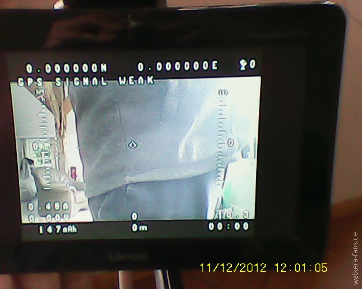
Funktionstest
AV-out (gelb/schwarz) ist rausgeführt, jetzt noch AV-in (rot/schwarz) wieder rein und es klappt!
Fertig
Erfolg!
Erwähnt werden sollte vielleicht noch, dass jeder Umbau:
- auf eigenes Risiko geschieht und
- die Garantie für das Gerät dahin ist!
Aber das weiß natürlich jeder…
Ansonsten viel Spaß beim Umbau und achtet auf die Schrauben … insbesondere die für das Kameramodul! Nach fest kommt lose 😉
Vielen Dank an den Walkera Fan Senkblei für die Bilder und die Beschreibung seines Umbaus!
Klasse Anleitung 🙂 kann OSD empfehlen, vorallem wenn die Kamera für FPV an einem Gimbal hängt
Hello,
I wonder if the son is 2 x 2 video output and video input!
Have you wiring diagram MinimOSD to DEVO‑M!
thank you for your site
Noch ein Nachtrag: Wenn kein Videosignal gesendet werden soll, die Stiftleiste nicht verwenden, die Verbindung getrennt lassen.
Die Kamera funktioniert dennoch!
Sieht bei meiner Ilook+ alles komplett anders aus, habe nur 3 leitungen die in den sender gehen und am Cameramodul einen 6 poligen Stecker. Die kabelfarben scheinen noch übereinzustimmen. Habe einfach das blau und das gelbe kabel im Kabelbaum gekappt, zum minimosd und zurückgeführt, Kamera sendet noch Bilder wenn das OSD aus ist, sobald das aber Strom bekommt ist das Bild weg. Keine Ahnung warum bin völlig Ratlos.
Die Ilook+ funktioniert ohne OSD und 2 „oldscool jumpern” immernoch wie gehabt. Gehe mal davon aus das mein OSD Schrott ist, was man so liest sind die Dinger entweder von Werk aus im Eimer oder von so mieser Qualität das man ein paar verheitzt bevors funktioniert.
Hi everybody.
Thank you, Gektor, for this good and useful mod but I’m sorry to be a little confused with this.
On the top pics from the camera module, in the original wiring, we see 6 wires.
On the „AV-out on the camera module according Umnbau (back)” we only see 2 wires and it’s very dificult to see if is the red wire remain or not.
What happende to the red, yellow (audio), white and grey wires ?
On this mod the red wire remains on camera and tx modules ?
Thank you in advance for your comments.
Hi Pedro, let me give the answer for I did it …
There are still 6 wires remaining, no changes!
The idea/solution is to cut inside the iLook only the two wires „AV” and „-” (bue and black, leading from camera modul to the TX) and bring them out of the box.
That means: „AV” and „-” from the camera modul out of the box and „AV” and „-” back into the box connected with the TX.
All the outher wires are untouched!
Hope it helps … otherwise I prepare a drawing.
Thank you so much for so quicly reply and that helped me.
I did this mod on my iLook but some problems happened because I received the video signal but on Devo F7 the stock information as model nr, the bottom values of throtle, etc, the voltage of the F7 are acting like crazys on the screen blinking in several places on the video.
This is without OSD connected, only the 2 wires connected themself. I don’t find the motif and I verified a small break on the video quality.
I didn’t solder the wires directly but cutted on the middle between camera and ts modules.
Then I solder long wires from there to the exterior:
– from cam module : blue on blue and black on black
– on tx : blue to blue and black to black (I identified each wire with IN and OUT).
I could change the colors but I prefered labeling the wires to avoid mistakes.
I have to disassemble again the iLook and verify what is going on, Pehraps should be better to solder the wires directly than solder wire to wire.
Thank you. Regards
One more thing :
the iLook works at 12v by a lateral JST connector coming from the QR.
As we are not taking from there the 12v needed for the OSD, the 12v for the OSD is from the QR ?
I verified one thing : only the 2 wires (video and ground) from and to the iLook connected to the 4 points on the analog side of OSD.
Only works if we inject 12v on the 12v IN pin.
So far as I understood:
There are different powersupply for iLook and OSD? In this case you should connect the ground to both accus outherwise it can‚t work.
Wire to wire is not a problem, don‚t forget to isolate the soldering.
Soldering directly on the PCB is a litte bit „tricky” for the soldering points are very narrow.
Good luck, it works!
Hi !
Thank you Gektor and Uwe.
I didn’t soldered directly, I cutted the wires and soldered extensions in both ways and add a small tube shrinked in each one.
I have full details on OSD and and corrected the voltage also.
Could be the Devi F7 but I didn’t have vídeo from the iLook, only OSD.
I inputed 12v from a extra 12v point from the board (extra 3 12v connections) on the analog side of the Mavlink OSD on IN but no out wire I have because the cam as self powered. I think this is not the motif I don’t have vídeo.
Monday I receive my Boscam monitor and I’ll see that.
Regards
Try one thing: Connect (only) all „-” wires together for if there is a second power supply the video needs another potential. Only minus (ground) … Ground from your 12V supply and ground from the external powersupply of your cam.
Outherwise it can‚t work.
Hope it works …
Unfortunally I can‚t send a drawing … sorry!
Thank you, Uwe ! No drawing is needed.
Today I’ll solder a ground wire at side of the 12v connection and will connect to pin „-” on IN at analog out section.
The 2 black wires ground from and to camera (one caming out from cam modulo and other to the tx module I’ll connect together as it was before I cutted the wires and made the extensions.
On this scenario we have the self powered cam with their own „+” and „-” and the OSD with a
„+” and „-” from the QR independents from cam.
In last chance I’ll cutt the red wire of power from cam to tx module and do the same thing I made to
the other 2 wires black and blue.
The problem would be that OSD will have the analog part powered by cam.
I’ll do a try tonight.
Thank you. Regards
Pedro,
now there is a drawing added by „Gektor”. That is the way I did it – and it works perfect.
If there is an own powersupply inside the cam you need only black and blue, no red!
OK I already seen that drawing but if I made like that and I don’t receive OSD.
Only inputing 12v on the IN pin. And no OUT 12 v pin.
With such configuration you get only one flashing red led but it must 2 red leds to works OK.
I don’t know ! Perhaps I made something wrong but if we are talking of cutting the signal of
video and ground between camera and tx modules and bring them to the outside to be connected on Mavlink OSD (IN for 2 wires from cam and 2 wires OUT to the TX module) that’s what is made on my case.
Beside that sketch, if you say taht works well, what you have on the side of OSD analog pins ?
And about 12v IN/OUT pins on analog side of OSD ? Do you have connections ???
OK I already saw that drawing but if I made like that and I don’t receive OSD.
Only inputing 12v on the IN pin. And no OUT 12 v pin.
With such configuration you get only one flashing red led but it must 2 red leds to works OK.
I don’t know ! Perhaps I made something wrong but if we are talking of cutting the signal of
video and ground between camera and tx modules and bring them to the outside to be connected on Mavlink OSD (IN for 2 wires from cam and 2 wires OUT to the TX module) that’s what is made on my case.
Beside that sketch, if you say taht works well, what you have on the side of OSD analog pins ?
And about 12v IN/OUT pins on analog side of OSD ? Do you have connections ???
http://www.droneshop.com/osd/mavlink-osd-p-69742.html
Here I found a sketch about connecting the modul with cam and TX.
In this picture there are cam, TX and the OSD-modul supplied by only one Lipo (3S).
If your cam has its own accu try to cut only the +12V in, the red wire leading to the cam.
Btw: My OSD modul is another (Tiny Mini OSD)
Ha,
Walkera consistency! With mine, 3 wires into the video TX are white (-), Red AV, and last, top wire in your „TX 5803 in the ilook in the original” photo is green.
That wire is interesting. It is _almost_ at ground potential, on the oscilloscope except with about 14k resistance to ground. I wonder what the green wire does.
The video signal has about 37(!) ohms resistance to ground with the device off.
In order to make the mod as robust and flexible as possible, I soldered two pin-strips together to make two 3 conductor male servo plugs. I seated the strips into the case slot that I cut, with the pins pointing inwards and outwards. On the internals, I used a servo lead to splice on to the video signal. On the outside,
This means everything can be safely unplugged at any time, and nothing to break off, or chafe and short.
When not using the OSD or external transmitter, or both, one can simply put an old school jumper plug on to connect video in and video out on the 3 pin plug.
Regards,
Joe
Hallo Sleat,
Could you please mail a picture of how you made this robust connection. I would like to add a camera switcher so i can switch between the fixed fpv camera ( look) de gimbal camera (Mobius). Is there a channel on the devo F7 that can do so ?
greetings from Belgium.
Jean-Pierre
I have a few photos of the iLook+ video out/in/ground plug. But how to post them?
OK, finally got time to re-disassemble the unit (it’s very fiddly and tight inside) and take a good photo.
https://plus.google.com/photos/101698509493312794817/albums/6136069640843079937
That should be sufficient for you to duplicate my setup!
Let me know if you have any questions.
Hi all,
I find this website very usefull, shame it’s in german but the google translator does it job.
I did the ilook+ mod with the minim osd module. I uploaded the latest minim osd extra firmware and tuned the pannel like i wanted.
When i start the copter. The osd data glitches a bit but still readable. Once the motors starts spinning the telemtry dissapears almost completely. Any idea what can resolve this issue ?
Greetings Alex
How are you powering the MinimOSD?
I power mine on the 5V side from the „data port”.
This is probably not the best idea, as I’m not sure what the design loads are meant to be for this port, but a 5V BEC could easily be incorporated for the 5V (3DR Radio and MinimOSD) parts.
The 12V side of the MinimOSD is powered by the 12V „accessory jacks” under the TALI H500 body, which are self-locking molex plugs, I believe.
There is some evidence that powering my accessories with 5V from the data port may affect the compass, not in a direct magnetic way, but in a „voltage droop/noise” way.
I plan to power my 3DR radio and compass (and gear servos) from a „nonessential DC buss” which I will make by running an additional hi-current 5V BEC off the main battery buss.
Good design dictates that absolutely nothing should be able to interrupt good voltage/current to the ESCs, FCS, and Receiver.
I’d also add that when calibrating the system magnetically, best practice would be to disable ALL the addon accessories like 3DR Radios and MinimOSD, maybe even the gimbal. In other words, the compass/radio/gps/fcs computer stack should have the best possible noise free voltage and current.
In the iLook+ camera has 3 wires (red-white-green up) and 2 ( yellow-black bottom), going from cam to the transmitter.
Which of these cables must connect, to send images to an external transmitter, like the immersionrc 600mw 5.8ghz?
i have 3 photo …
http://i64.photobucket.com/albums/h166/kafeneio-megalopolis/DRONES/ILOOK/1_zpsgiehgkub.jpg
http://i64.photobucket.com/albums/h166/kafeneio-megalopolis/DRONES/ILOOK/2_zpsdniyuzj7.jpg
http://i64.photobucket.com/albums/h166/kafeneio-megalopolis/DRONES/ILOOK/3_zps3kdjvvgy.jpg
Hi Panos,
The colors do vary, unfortunately, from camera to camera.
Have a look at this image:
https://plus.google.com/photos/101698509493312794817/albums/6136069640843079937
You can see, on the left, the nearest wire is orange, video „in” from the outside world to the iLook+ inbuilt transmitter. This can be any video source!
The next wire (red) is „out” which is the video the iLook+ is capturing, or seeing.
The furthest wire (brown) is „earth”. I soldered it to the transmitter case.
So, to answer your question, and assuming your wires are the same colour as mine (Walkera changes sometimes) looking at the transmitter body in the photo, it looks like the middle wire which _was_ the red one in the photo, goes from the camera unit to the transmitter, and sends the video to the outside world.
That wire, plus an „earth” connection (where I used a wire to the transmitter case shield) should give you reasonable video. It does for me, as my external connector passes through the minimOSD and back to the transmitter inside the unit.
Feel free to duplicate my setup, it took about 2 hours to build, since the most part was drilling and filing a proper hole in the back of the unit, in the right place, and mounting an insulated (the case is very conductive!) gland made of epoxy to hold the fingers securely. With that setup, you can simply plug servo connectors in on both sides for convenience!
For „normal” operation, I use an old PC „jumper” connector to connect video-out to video-in, and when using minimOSD, I bring the video out through that unit and back into the back of the iLook+.
Big thanks to Joe – did the mod as he proposed – and it works very nicely right from the start: no problem at all.